If you are designing for a printer you have never measured, leave 0.5 mm between mating FDM parts. That is the figure Protolabs Network publishes, and it is more than double the 0.2 mm that circulates on forums. On your own calibrated machine you can go tighter, but find the number with a test print instead of borrowing someone else’s.
What the design guides publish
| Fit | Published figure | Who says so |
|---|---|---|
| Snap-fit connectors | 0.5 mm clearance | Protolabs Network’s snap-fit design guide |
| Interlocking joints | 0.5 mm for FDM, against 0.2 mm for SLA and SLS and 0.1 mm for injection molding | Protolabs Network’s interlocking joints guide |
| Tight sliding fit | 1 x extrusion width | AON3D’s engineering fits guide |
| Running fit, free movement | 2 x extrusion width | AON3D |
| Press fit | no interference figure; clearance fit plus 0.2 mm crush ribs | AON3D |
Two of those rows need explaining.
AON3D, a printer manufacturer, ties clearance to extrusion width instead of quoting a constant, on the grounds that the extruded bead tends to bulge slightly past its theoretical path. Its example is a 0.6 mm nozzle with a 0.75 mm line: 0.75 mm clearance for a tighter sliding fit and 1.5 mm for a running fit. Apply the same rule to a 0.4 mm nozzle with a 0.45 mm line and you get 0.45 mm and 0.9 mm. The sliding figure lands almost exactly on Protolabs’ 0.5 mm, which is a decent sign that two independent sources mean the same thing. It also means that fitting a bigger nozzle loosens every fit you have already designed; the 0.6 vs 0.4 mm nozzle guide covers the other trade-offs.
Neither source says whether its clearance is per side or across the diameter. I read both as the total gap, since that is how AON3D’s worked example is phrased (“clearance between mating parts”), but test before you commit a design to it.
The press fit row is the interesting one. Nobody I could find in a maker’s or service’s guide publishes an interference value for FDM, and AON3D explains why: a round printed hole can only open up by stretching around its circumference, which tends to crack or delaminate the part. Its alternatives are to use hexagonal or square sections, which need less stretching and let you hide the seam in a corner, or to design a clearance fit and add vertical crush ribs 0.2 mm tall that deform on assembly. Sloping the bore or shaft by about 2° and adding the ribs gives a transition fit. Straight ribs along the full length give a true press fit, which AON3D says is for one-time assembly only because repeated use wears the interference away. If a forum post hands you “0.1 mm interference for a press fit”, that is one person’s printer and one filament.
Why the published figures are so loose
Protolabs Network’s dimensional accuracy guide gives desktop FDM a tolerance of ±0.5 percent with a lower limit of ±0.5 mm, and industrial FDM ±0.15 percent with a lower limit of ±0.2 mm. The lower limit is what matters on small parts. An 8 mm pin is ±0.04 mm by the percentage and ±0.5 mm by the floor, so the floor governs.
Follow that through. An 8 mm pin and an 8.5 mm hole, each allowed to be off by 0.5 mm, can still collide in the worst case. That is a service quoting what it will guarantee on any machine, with any operator, and it is deliberately pessimistic. It is the right assumption when you send a file to a print farm or publish a model for strangers. It is too pessimistic for a printer you have tuned yourself, which is why a personal number is worth having.
Two errors that are not random
Random scatter you can only allow for. Two FDM errors are systematic, and you can design or slice them out.
Holes print small
Protolabs Network’s FDM design guide describes the mechanism: as the nozzle lays the perimeter of a vertical hole, it presses the new layer onto the one below, and the squeezed bead spreads into the hole. The effect is worse on small holes because the bead is large relative to the diameter. How much depends on printer, slicer, hole size and material, and Protolabs says several test prints may be needed. For a critical diameter its advice is to print undersize and drill to size.
Slicers give you two other tools. The OrcaSlicer precision settings include X-Y hole compensation, where a positive value grows every hole in the XY plane, and X-Y contour compensation, which does the same for outside dimensions. Orca also offers polyholes, which turn round holes into polygons with fewer, flat sides that sit on the outer boundary of the hole, an idea Orca credits to the Hydraraptor blog.
The same page explains a quirk worth knowing if your outside dimensions run large. Slic3r-family slicers, which include PrusaSlicer and OrcaSlicer, model the bead as an oval and overlap neighboring walls, so two 0.4 mm walls at 0.2 mm layers measure 0.714 mm, not 0.8 mm. When inner walls print first, that overlap can push the outer wall outward. Orca’s Precise wall option sets the overlap between the outer wall and its neighbor to zero to stop that.
The first layer flares
The first layer is squashed into the bed to make it stick, so it comes out wider than the layers above. Everyone calls it elephant foot. It matters for fits because the flare is at the exact edge where two parts meet on assembly.
Prusa’s elephant foot compensation article says the slicer can shrink the first layer to cancel it, that about 0.2 mm usually works for a 0.4 mm nozzle, and that Prusa’s own profiles ship with it on. A brim that looks detached in the preview is expected; if it is detached on the real print, the value is too high.
OrcaSlicer lets you spread the correction over several layers, tapering linearly. With 0.25 mm over 2 layers, the first layer is pulled in 0.25 mm and the second 0.125 mm. Over 5 layers it runs 0.25, 0.20, 0.15, 0.10, 0.05 mm. Orca lists the causes as the weight of material above, thermal expansion, a bed that is too hot and inaccurate leveling, so if you need an unusually large value, check the bed temperature against your filament’s data sheet on the temperature table and revisit the first layer guide before you compensate for a fault.
The design-side fix costs nothing: Protolabs recommends a 45° chamfer or a radius on every edge that touches the build plate when assembly matters.
Finding your own number
The OrcaSlicer tolerance calibration page describes a built-in test model: a plate with six hexagonal holes at 0.0, 0.05, 0.1, 0.2, 0.3 and 0.4 mm clearance and a hexagonal tester, which you can also check with a 6 mm Allen key. Right-click the plate, Add Handy Model, Orca Tolerance Test.
Here is how to read it. Say the key drops into the 0.3 and 0.4 holes, pushes into 0.2 with thumb pressure, and will not enter 0.1. On that printer, with that filament, 0.2 mm is your snug fit and 0.3 mm your sliding fit. Those are less than half the published 0.5 mm, which is the gap between a guarantee and a measurement.
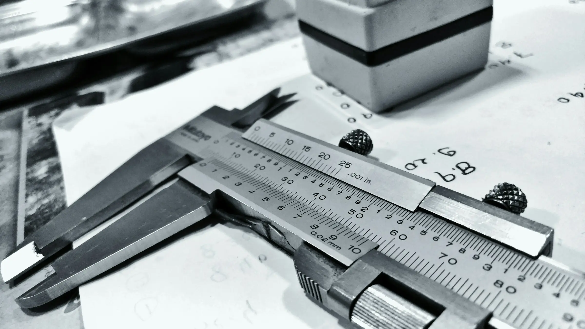
Then measure the holes and the tester with calipers, as Orca instructs. If a nominal 6.00 mm tester measures 6.08 mm and the holes are all small by a similar amount, you have a systematic error, and X-Y contour and hole compensation will take it out. Adjust, reprint, repeat. Orca’s page notes that results differ between printers even with the same filament and profile, and between filaments on the same printer, so redo the test when you change material. AON3D makes the material point too: semi-crystalline polymers such as nylon generally shrink more, and larger parts need more allowance. A fit tuned in PLA will not carry over to PA6 or carbon-fiber nylon.
One design habit follows from all this: where you can, orient the part so its mating face is not the one on the bed. That takes elephant foot out of the fit entirely.
If everything measures fat, walls and pins alike, look at extrusion before tolerances. Protolabs lists over-extrusion among the causes of dimensional error, and fixing it starts with extruder calibration, which the e-steps calculator walks through.